-
MVP
Step 1: Cutting and Assembling Pieces
The goal for this week was to create a minimum viable product for my final project. I wanted to make a basic robot that could sense distance to walls (of the maze) and move based on that.
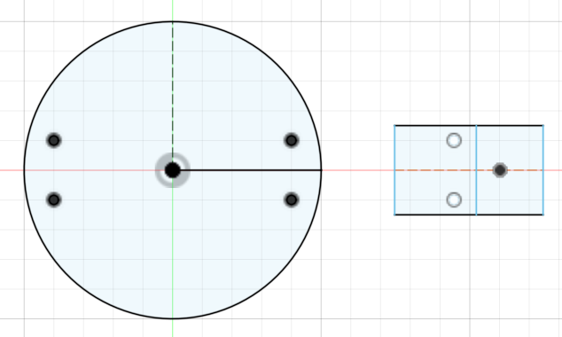
The first step was to make the circular base and the pieces that connect the wheel and motor to the base. I designed the pieces in Fusion 360 and then laser cut them out of cardboard. (I used a relatively cheaper material for prototyping.) The vertically aligned holes allow two M3 screws and nuts to attach the base to each rectangular piece, and the motor shaft goes through the third hole in the rectangular piece. The rectangular piece is scored so that it can bend.

Fusion 360 Design 
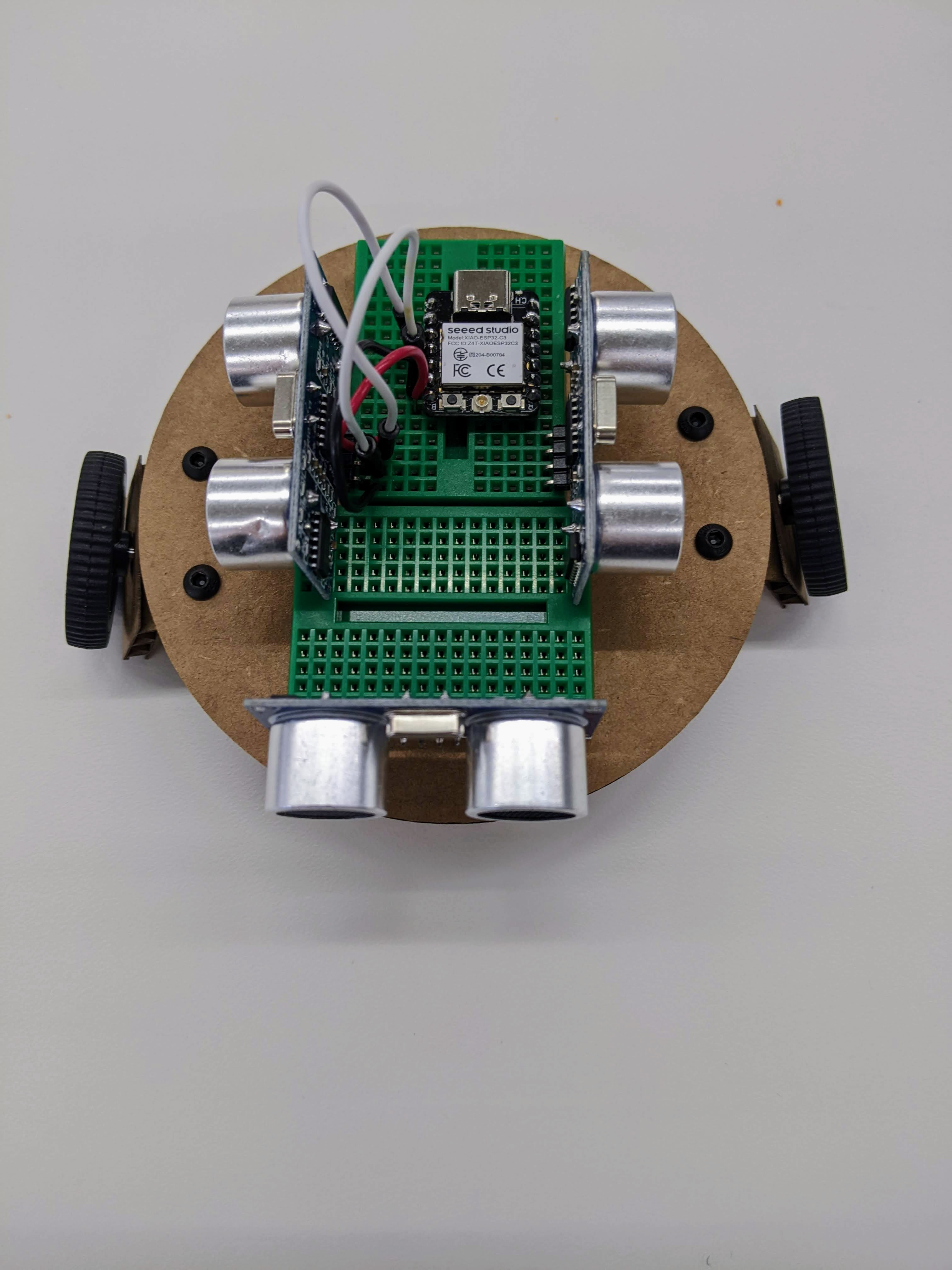
Robot Prototype 
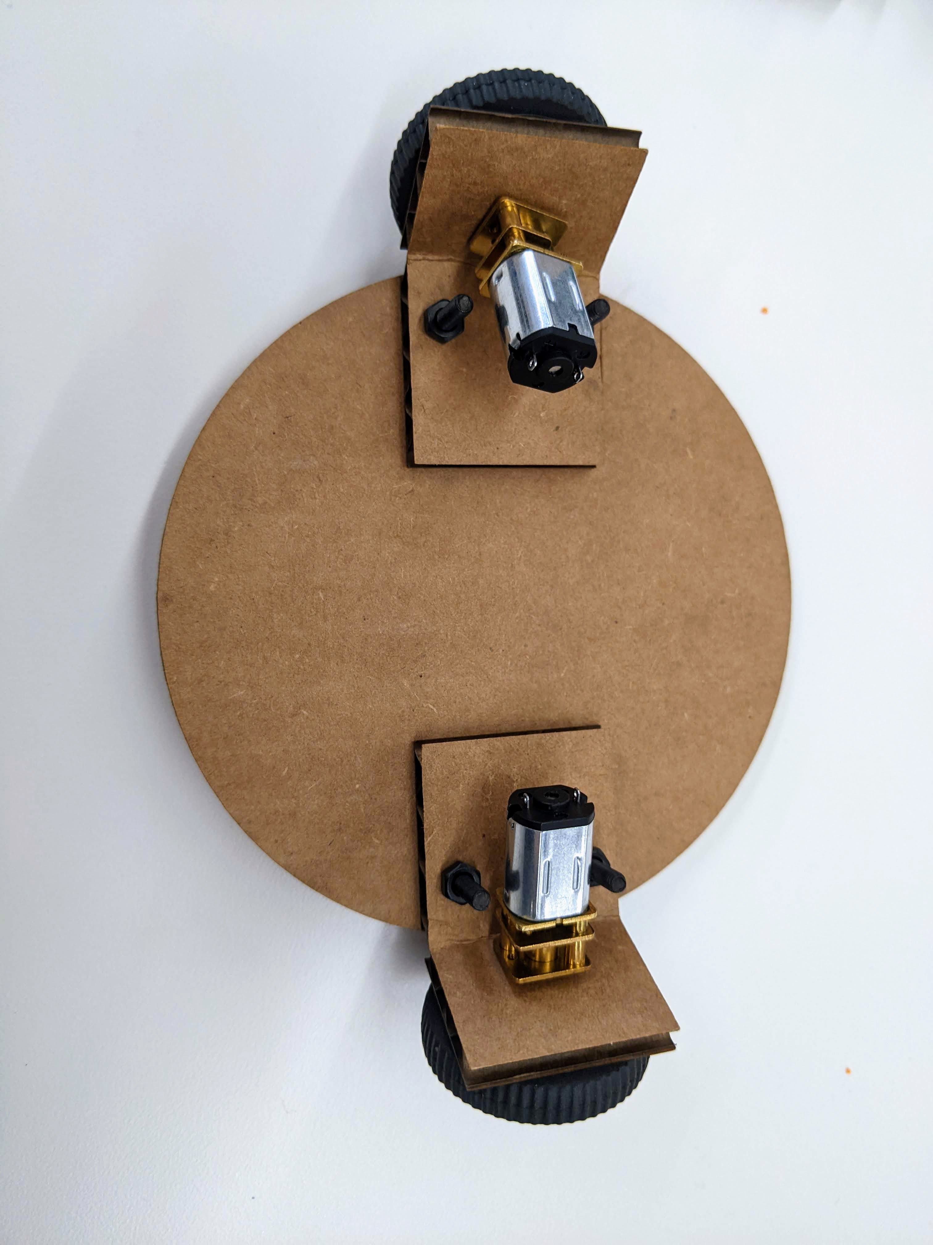
Bottom of Robot Prototype Future improvements and questions for Step 1:
Use a more durable material for the base, such as wood, and 3D print the rectangular pieces since they have a 90 degree bend.
Secure the motors to the bottom of the base. (I think this will actually be fixed automatically once I 3D print the pieces; they are popping up at the moment because the scoring in the cardboard cannot maintain a 90 degree angle.)
Secure a power bank on the base. Are there small and light ones available? This may involve making the base larger.
Add a wheel in the front that can swivel to help the robot balance. Are there smaller ones?
Step 2: Sensing and Motors
The second step was to make the ultrasonic sensors sense walls and turn motors accordingly. I started with the ESP32 since it is smaller than the Arduino Uno and would fit on the breadboard without requiring a second circular base layer of the robot. I used the same code from last week's assignment, but changed the pin names to the correct ones. I combined the ultrasonic part of the circuit from last week with the motor part of the circuit from Week 4's assignment. However, the sensor was extremely unreliable (unlike last week); most of the time it read a signal of 0 with occasional random positive numbers mixed in. I realized it might be because the connection between the pins and the ESP32 was not good, so I soldered header pins into the ESP32 and rewired the circuit. Unfortunately, this did not fix the issue, so I decided to put the ESP32 away for now and try to get the mechanism working first on the Arduino Uno.
I first modified the code from last week so that the output device was a motor instead of an LED. This involved creating a
Motorclass with asetSpeedfunction that would make the motor rotate when the sensor signal was greater than some threshold. I used trial and error to find a reasonable threshold.class Ultrasonic { public: int trigPin; int echoPin; int signalInterval; unsigned long signalStartTime; int measured = 3; Ultrasonic(int pin1, int pin2, int interval) { trigPin = pin1; echoPin = pin2; signalInterval = interval; // in microseconds pinMode(trigPin, OUTPUT); pinMode(echoPin, INPUT); } void sendSignal() { if ((micros() - signalStartTime > signalInterval) && (measured == 3)) { signalStartTime = micros(); digitalWrite(trigPin, LOW); // Set the Trigger pin LOW to start a pulse measured = 2; } else if ((micros() - signalStartTime > 2) && (measured == 2)) { digitalWrite(trigPin, HIGH); // Set the Trigger pin HIGH measured = 1; } else if ((micros() - signalStartTime > 12) && (measured == 1)) { digitalWrite(trigPin, LOW); // Set the Trigger pin LOW again to complete the pulse measured = 0; // Signal is done so ready to measure } } int measureSignal() { if ((micros() - signalStartTime > signalInterval) && (measured == 0)) { long duration = pulseIn(echoPin, HIGH); // Listen for a pulse on the Echo pin Serial.print("Duration: "); Serial.println(duration); measured = 3; return duration; } } }; class Motor { public: int motorPin; int speed; Motor(int pin) { motorPin = pin; pinMode(motorPin, OUTPUT); } void setSpeed(float duration) { float val; if (duration > 425) { val = 150; } else { val = 0; } analogWrite(motorPin, val); } }; void setup() { Serial.begin(9600); } Ultrasonic ultrasonic(9, 10, 1000); Motor motor(6); void loop() { ultrasonic.sendSignal(); float duration = ultrasonic.measureSignal(); motor.setSpeed(duration); }This mostly worked! If you look at the front wheel really closely in the video, you can see it turning until the wall of the box gets close enough to the sensor, at which point it stops turning.
The alligator clips kept falling off since the tabs on the motor were so small, so I soldered wires to the motor tabs instead. I then modified the
loopfunction to set both motors together and migrated the entire circuit to the small breadboard. This is the result! Although the wheels are turning, the robot doesn't quite move because the cardboard piece is not letting it touch the ground. This will hopefully be fixed once I 3D print the piece and the motor is completely flat against the bottom of the base.Future improvements and questions for Step 2:
Figure out why the ESP32 is not working. :(
Wire up the other two sensors (facing the left and right).
Next Steps
Next week, I'll work on turning. In the first iteration, the robot will go to a cell and turn in place, rather than moving in curved lines. To turn in place, the two wheels on either side will rotate in opposite directions at the same speed. To turn in a curved line, the two wheels rotate in the same direction at different speeds.