-
We covered the basics of programming, the Arduino board, and electronics.
Arduino Program
The assignment was to program an Arduino board to do something, so I decided to adjust the speed of my kinetic scultpure from last week. Due to the unadjustable 5V power source, the flower bloomed at an extremely fast (unideal) speed...
Flower Sculpture from Last Week In lab, we used a potentiometer to allow a user to dynamically control the brightness of an LED. A potentiometer is a variable resistor with three pins. When the external sides of the potentiometer are connected to voltage and ground, the middle leg will give the difference in voltage as you turn the knob.
analogRead()outputs a value between 0 and 1023, a representation of the voltage on the pin.We also used the L9110 H Bridge Power Driver to control the speed and direction of a motor. The
analogWrite()function uses a technique called Pulse Width Modulation (PWM). PWM turns the output pinHIGHandLOWover a fixed period of time in extremely fast intervals. The percentage of time a pin isHIGHin a period is called duty cycle. The argument ofanalogWrite()that controls this setting takes values between 0 and 255.
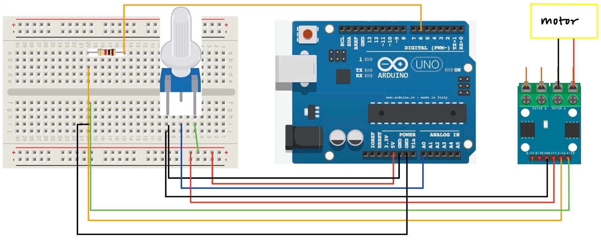
PWM 50 Combining these two techniques, I built a circuit that uses a potentiometer to control the speed of the motor's rotation! I also made a few modifications for my use case:
-
The digital pins on the Arduino did not supply enough current to turn a motor (the LED required much less current), so I had to edit the circuit so that the motor also used the 5V pin.
-
The motor did not turn with less than ~100 speed. Hence, instead of mapping the 0-1023 range of the potentiometer to the full range of 0-255 speed, I mapped it to 100-255. This way, no matter where the user turns the potentiometer knob, the flower will always be blooming. :)
I found the serial prints really helpful for debugging and making sure that my
potValandmotorValvariables were updating correctly. My final code is below:const int potPin = A0; // define Analog In pin A0 for the potentiometer int potVal; const int motorPin = 6; // define Digital pin 6 for the motor int motorVal; void setup() { // runs once Serial.begin(9600); pinMode(potPin, INPUT); // specify potPin as input pinMode(motorPin, OUTPUT); // specify motorPin as output } void loop() { // loops forever potVal = analogRead(potPin); // read in the potVal from potPin motorVal = map(potVal, 0, 1023, 100, 255); // map potVal range to motorVal range analogWrite(motorPin, motorVal); // write the motorVal to motorPin Serial.println(motorVal); // optional print statement, can change motorVal to potVal for debugging }Here is a circuit diagram and schematic:

Circuit Diagram 
Circuit Schematic And here's the final product!
New Flower Sculpture -