-
This week, we learned how to use different saws, drills, and assembly techniques.
Kinetic Sculpture
The main assignment was to make a kinetic sculpture, including circuitry to move the sculpture. Inspired by the crank slider we created during lab, I brainstormed things that go up and down. Eventually, I landed on a flower blooming because I saw this cool art installation by studio DRIFT called Meadow consisting of upside-down mechanical flowers that open and close:
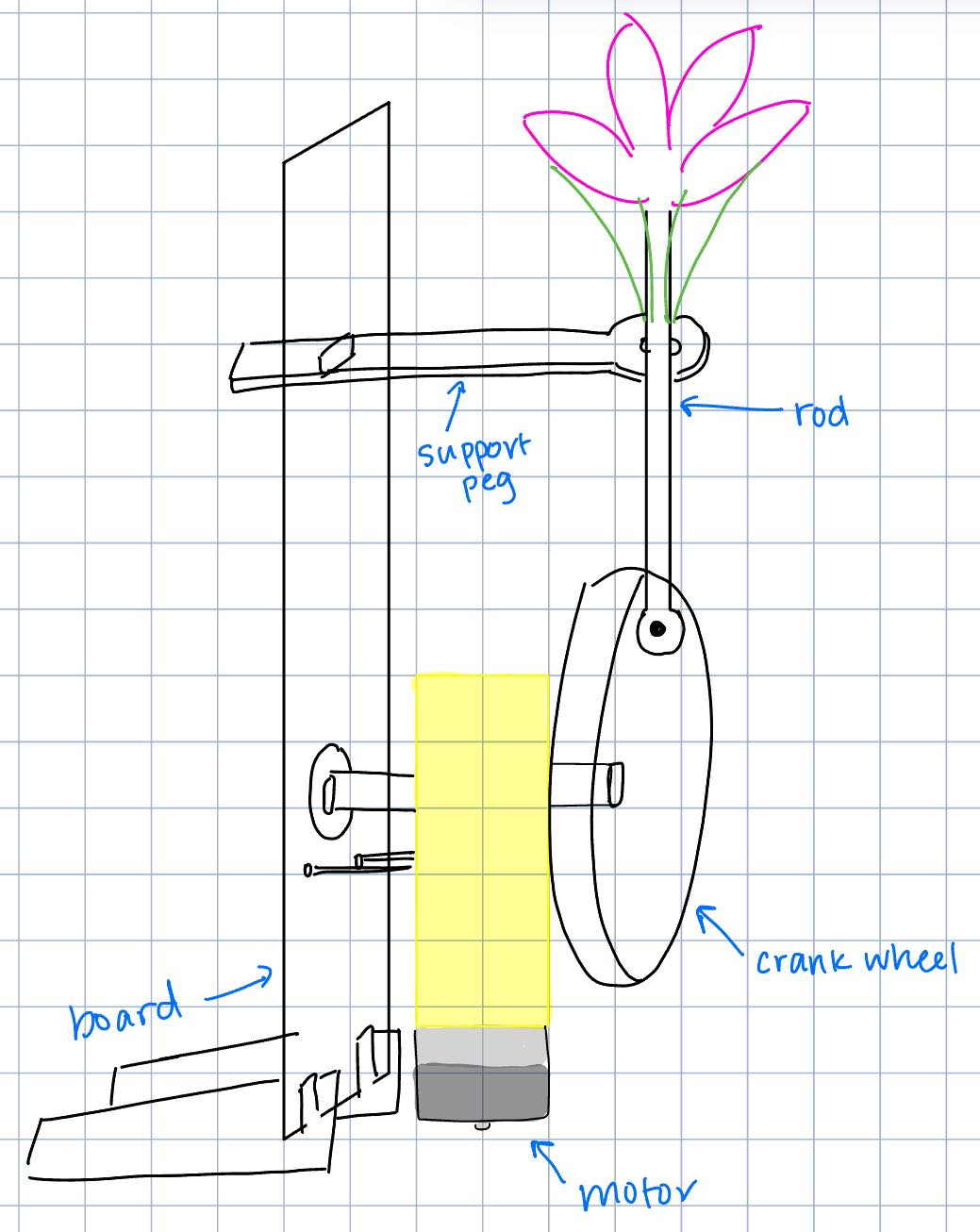
Based on this origami flower tutorial, my idea was to fix the support peg and attach the outer layer of paper sticks to the ring, then attach the inner layer of paper sticks to the tip of the rod. These will be stuck together, so that as the rod moves up and down through the ring (which stays fixed), the paper sticks open up and fold in. It was hard to draw this two-layer paper stick mechanism, but here's a sketch of the general structure of the sculpture.
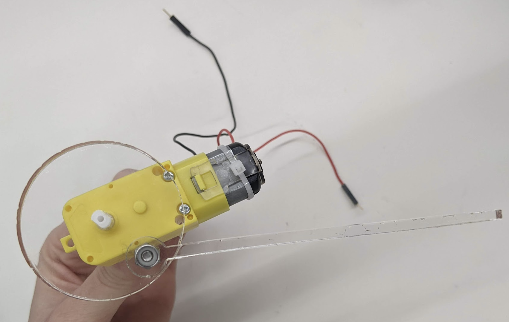
Sketch I started by modeling the crank wheel and rod from lab in Fusion 360. However, I wanted to press fit the crank wheel onto the motor, so I had to modify the center hole to be the right shape. I printed both components out of 6mm clear acrylic using the laser cutter. The rod was attached to the crank wheel using a screw and two nuts, and the final assembly of the three parts can be seen below. Luckily, everything fit together pretty well.
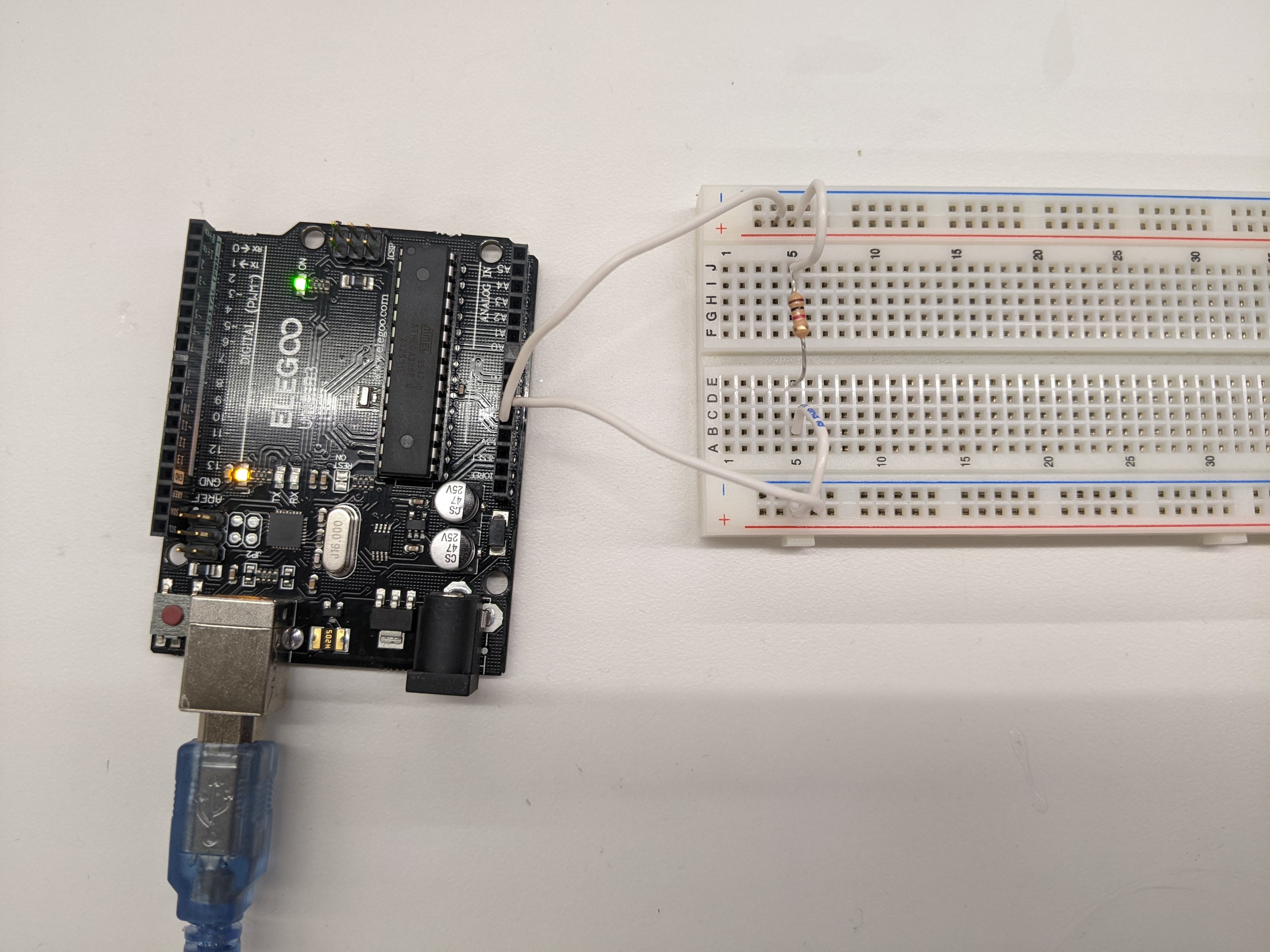
Assembly of Crank Wheel, Rod, and Motor At this point, I tested the rotation mechanism by building my circuit on the breadboard. The circuit itself was pretty straightforward; the power source was the USB to my laptop, and I added a 1 kΩ resistor.
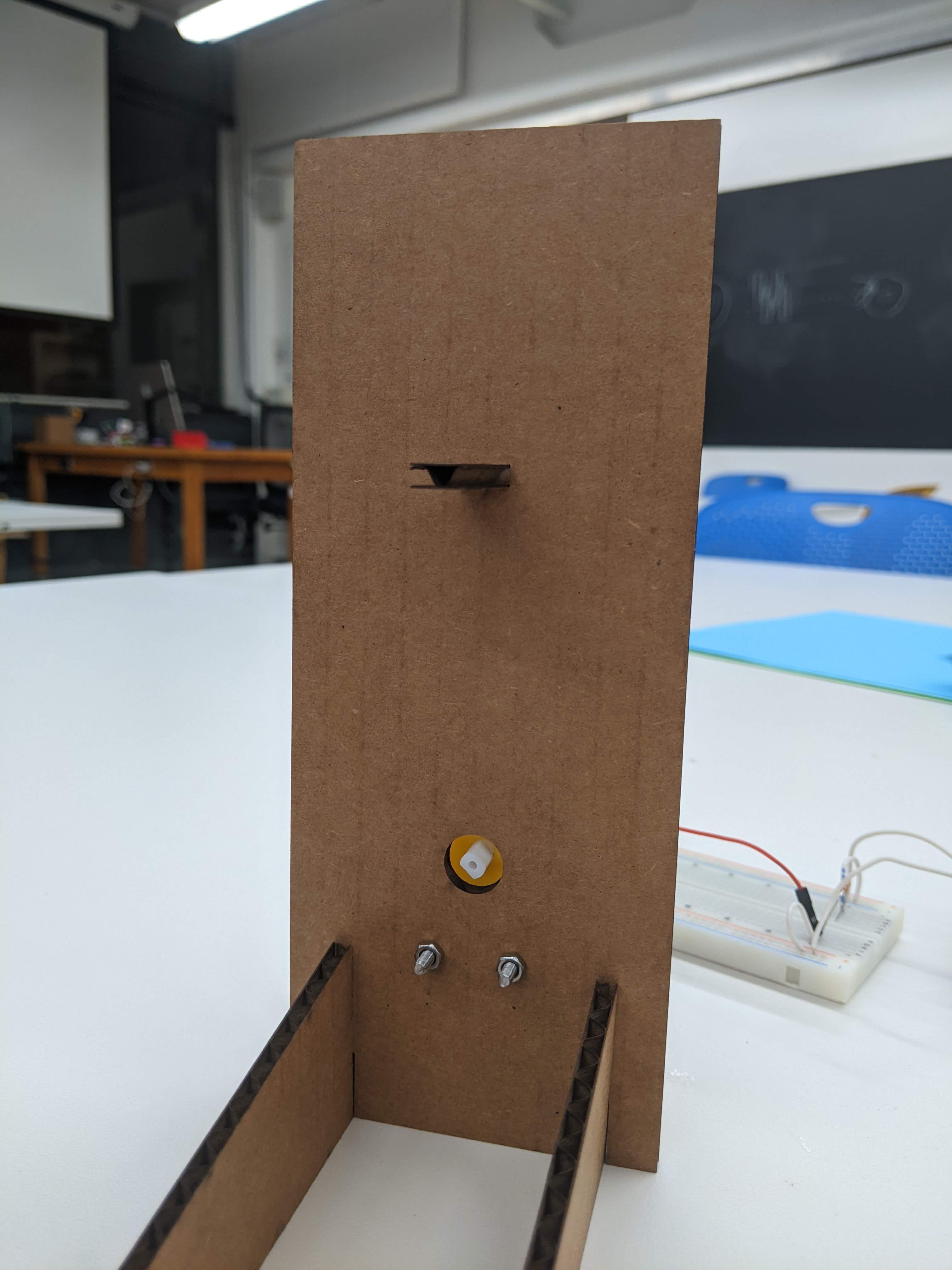
Circuit The next step was to build a board to mount the motor and support peg to. The board had two small circular holes that would be used to mount the motor with screws, and a larger circular hole so that the board would not interfere with the unused side of the motor spinning freely. Finally, I added a rectangular hole to insert the support peg through. Printing the board took a few tries as I shifted the holes around to find the perfect position and account for kerf (since the rectangular hole had to be pretty tight to hold the support peg up).
Back of Board 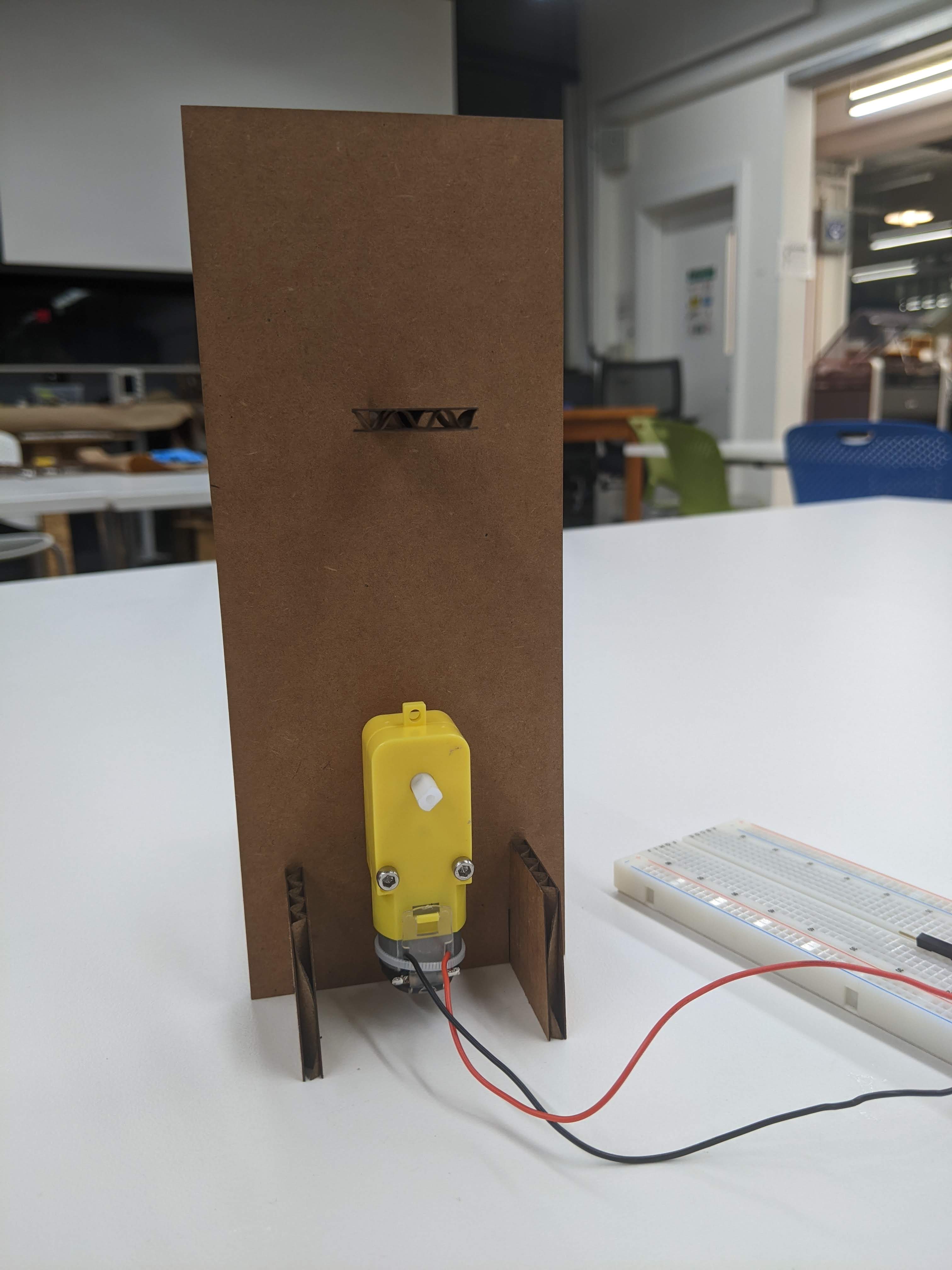
Front of Board The only issue with this arrangement was that there was nothing holding the crank wheel + rod onto the motor. Since the white part of the motor inserted into the hole was fairly short, the crank wheel would fall off as the motor spun. (See video above.) To fix this, I realized there was a tiny hole in the white part and I could insert a screw! However, the screw head was still too small to block the crank wheel, so I added a washer in between. This was sufficiently wide and blocked the crank wheel from falling off. Unfortunately, it created a new problem: the screw stuck out too much from the crank wheel and interfered with the rod spinning around. I finally fixed this by inserting three washers to add space between the rod and the crank wheel. The mechanism was complete!
The final step was to create the origami flower itself. Following the tutorial from before, I taped the paper sticks to the support peg and rod in the layered pattern. The final product is below!
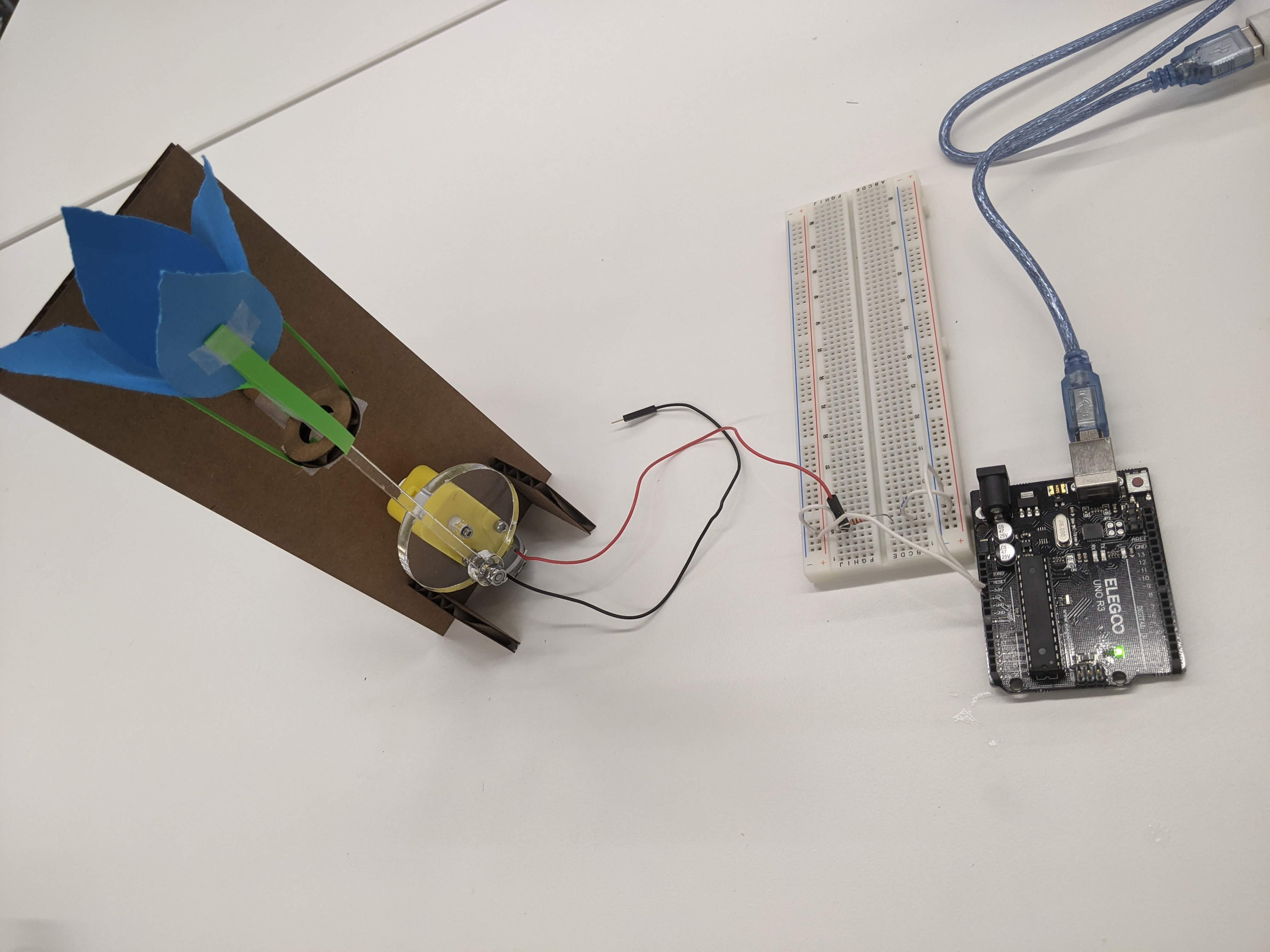
Final Setup 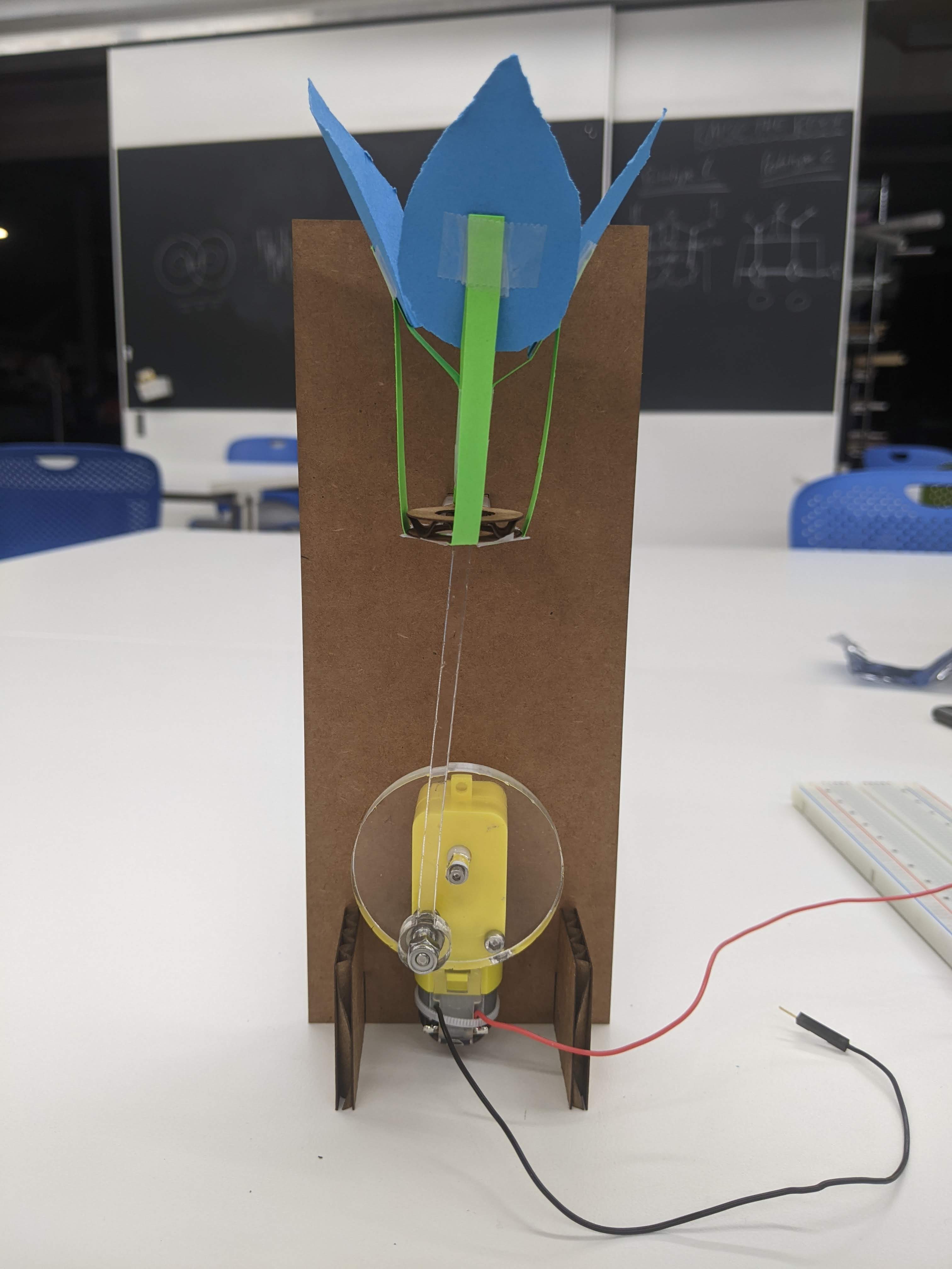
Final Sculpture Using the multimeter, I measured the voltage in my circuit to be 5.14V. Since we used a 1 kΩ resistor, Ohm's law tells us the current through the circuit is 5.14 mA.
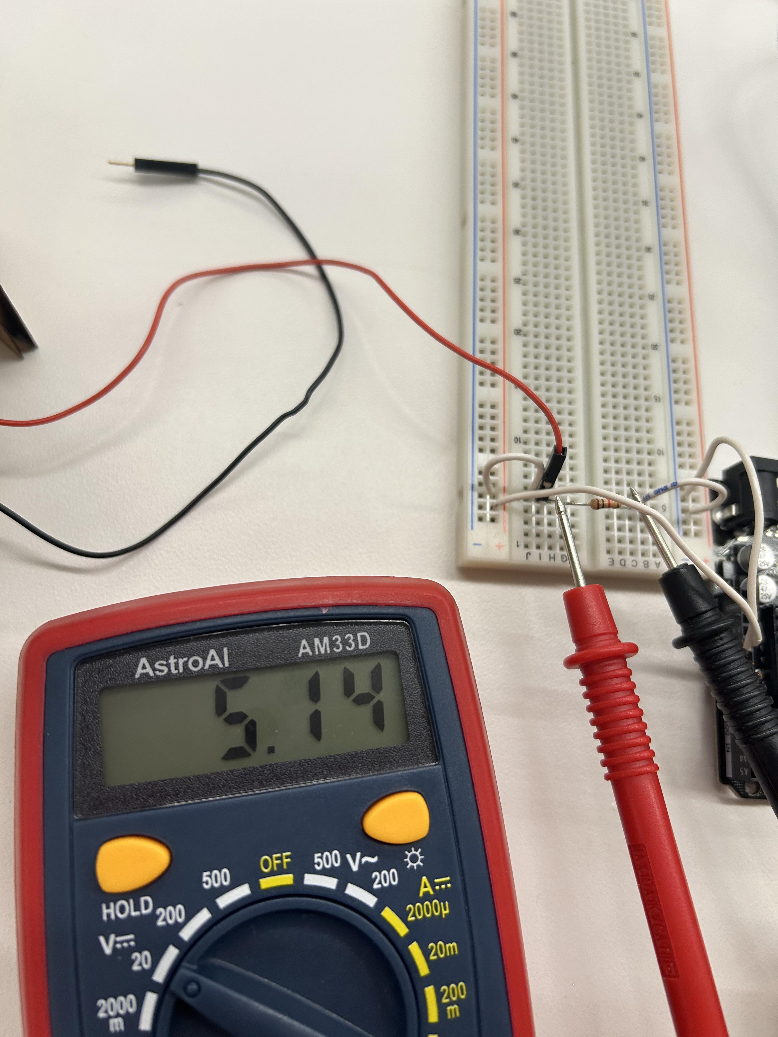
Multimeter Reading